
Read Construction Drawings to Produce Takeoffs That a UK QS Can Check

Check the title block, drawing index and revision status before you read a single line of the actual design. Then work through the set in order: site plan, floor plans, elevations and sections, details, then schedules and specifications. Every drawing and every spec sheet works as one instruction, and reading them separately is where most beginner mistakes start.
TL;DR:
Confirm the drawing revision date and sheet number before measurements to avoid errors from outdated versions or mismatched sheets.
Cross-reference plan, elevation, and section views to fully understand element sizes, locations, and construction details.
Always verify the scale with the graphic scale bar, and trust written dimensions over scaled measurements when discrepancies occur.
Use conventions like line weight, dashed lines, and cut lines carefully, referring to the legend to interpret symbols accurately.
Check specifications, notes, and material callouts separately from drawings to ensure accurate pricing and compliance with detailed standards.
Table of Contents
How do you read the title block and drawing index?
The title block sits in the bottom corner of every sheet, and it tells you whether you’re even looking at the right drawing. Get into the habit of checking it before your eyes drift to the plan itself.
Look for these fields every time:
Project name and number — confirms you’re on the correct job, especially useful if you’re juggling multiple sites.
Sheet number and title — tells you what discipline and what part of the building this sheet covers.
Scale — the ratio the drawing was produced at (more on why this matters below).
Issue date and revision status — the single most important field on the page.
Author or issuing practice — useful when you need to raise a query.
The drawing index, usually on the cover sheet, lists every sheet in the set using discipline prefixes: “A” for architectural, “S” for structural, “M” and “E” for mechanical and electrical, “C” for civil. A coordinated set typically runs cover sheet, index, and general notes first, then site and civil, then architectural, structural, and services sheets in that sequence. Revision clouds, the bubble or triangle shapes around changed areas, flag what’s altered between issues. If two sheets in your hands show different revision letters for the same area, stop and get the current issue before you measure anything. Always check the legend and general notes before you assume a symbol means what it meant on the last job. Standards keep drawings broadly consistent, but the project’s own legend overrides convention whenever the two disagree.
What do plans, elevations and sections each show?
Three views carry almost all the information in a typical drawing set, and each answers a different question. A plan is a horizontal slice through the building, showing where things sit. An elevation is a straight-on view of a face, showing what it looks like. A section is a vertical cut through the building, showing how it’s actually put together, floor build-ups, ceiling heights, structural depths. These roles rarely overlap, which is exactly why you need all three before you understand anything fully, a point that holds true across the core architectural conventions.
On a plan, a quarter-circle arc off a rectangle is a door swing, and its direction tells you which way the door opens into the room. Wall thickness on plan tells you construction type at a glance: a thin single line is usually a stud partition, a thick hatched block is masonry or concrete. The north arrow orients the whole building, and gridlines (usually lettered one way, numbered the other) give you a coordinate system for locating anything precisely.
Try this short exercise to see how the views connect:
Pick one window on a floor plan and note its grid reference.
Find the same window on the relevant elevation and check its height and material callout.
Locate the matching section, if one’s cut through that wall, and read the head, cill and lintel detail.
Check the window schedule for the exact size, glazing spec and any performance rating.
Do that once with a real set and the whole idea of cross-referencing stops being abstract.
How do you measure drawings accurately without errors?
Confirm the stated scale on the title block, then check the graphic scale bar printed on the sheet against it. The graphic scale is your safety net: if a PDF has been resized or printed at the wrong setting, the stated scale (say 1:50) becomes meaningless, but a graphic scale bar resizes with the drawing and stays accurate. Never scale off a printed or resized PDF without checking that bar first.
Written dimensions always beat scaled measurements. If a dimension string on the drawing says 2,400mm but your scale rule gives you 2,380mm, trust the written figure and query the discrepancy rather than splitting the difference.
A few conventions worth learning early:
Lineweight — heavier lines usually represent cut edges or elements closer to the viewer; lighter lines show things beyond the cut plane.
Dashed lines — typically indicate hidden elements: something above, below, or removed for clarity.
Cut lines — a jagged or chained line with an arrow shows where a section has been taken and which direction you’re looking.
Pro Tip: Keep a running list of every symbol you’re not 100% sure about as you go through a set. Resolve each one against the legend or general notes before you measure anything near it, rather than guessing and hoping it doesn’t matter.
How do you read structural and MEP drawings safely?
Structural and services (mechanical, electrical, and plumbing, or MEP) sheets carry the information that keeps a building standing and running, so they deserve more caution than architectural sheets alone. Start the same way you did with the architectural set: structural index, general notes, then the gridlines and datums that tie structural information back to the architectural plans.
From there:
Trace load paths — follow foundations up through columns and beams, checking reinforcement tags against the reinforcement schedule or detail they reference.
Check MEP routing against structure — ductwork, pipework and cable trays need to fit within ceiling voids and service zones without clashing with beams or slabs.
Flag anything touching openings — a duct crossing a doorway or a beam dropping into a window head height needs resolving before construction, not during it.
Stop at any conflict — if the structural drawing and the architectural drawing disagree on a dimension or a wall position, don’t guess which one’s right. Raise it with the engineer or log a formal query.
A beginner’s takeoff: a short, traceable estimating checklist
Estimating from drawings means combining the drawings with the specifications and schedules, never reading one without the other. A wall shown on plan tells you its location, not its full build-up, fire rating or fixings, and pricing it without the wall type reference is how quantities go wrong before work even starts.
A workable beginner process looks like this:
List elements by group — walls, floors, roof, openings, finishes, following an elemental structure rather than a random walk around the drawing.
Record units and source — for every quantity, note the sheet reference, the revision it came from, and the unit (m², m, number).
Apply an allowance — add a waste or wastage percentage appropriate to the material, and don’t forget preliminaries (site setup, scaffolding, temporary works) sit outside the measured quantities but still cost money.
Flag assumptions — anywhere you couldn’t confirm a detail, write down what you assumed and why, so it’s checkable later.
RICS NRM 2 sets out detailed rules for measuring and describing building work for bills of quantities, while NRM 1 gives the elemental structure used for early cost plans. Beginners rarely need to apply either standard in full, but building a takeoff that a professional quantity surveyor could follow and check is the right habit to form early, because a traceable record beats a single confident total every time, a discipline the RICS measurement framework is built around. The most common pitfalls are counting only what’s visible on one plan, forgetting waste and preliminaries altogether, and pricing off a superseded revision. Once a project moves past a rough budget figure, bring in a quantity surveyor working to NRM conventions.
Practice exercises that build coordination skills fast
Reading drawings well is closer to learning a language than memorising a symbol chart, and fluency comes from repetition on real sets rather than from a single tutorial. Tracing an element across plan, elevation, section and schedule is consistently the fastest way to learn how a set fits together, according to guidance on navigating construction documentation.
Three exercises worth repeating on different drawing sets:
Trace one opening — pick a door or window and follow it from plan through elevation, section, and into its schedule entry.
Measure and cross-check one wall run — take a dimension off a plan, then check it against the wall type note and any waste allowance you’d apply when pricing it.
Draft a discrepancy note — find one point where two sheets seem to disagree, and write the short, specific query you’d actually send to a designer or contractor.
Do each exercise on two or three different residential sets and the underlying pattern becomes obvious fast. Simple domestic plan sets, the kind used in extension or loft conversion applications, are ideal for this because the scale is manageable and the disciplines are limited.
What are the basic steps for measuring and estimating from drawings?
Boil the whole process down and it runs in a fixed order every time, regardless of project size.
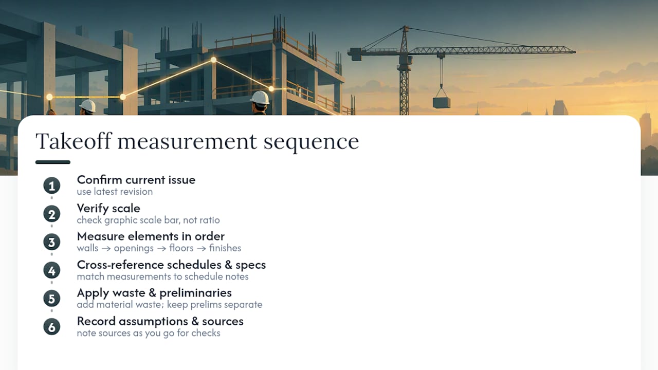
Start by confirming you’re working from the current issue, not a superseded one, because a measurement taken off the wrong revision is wasted work however carefully you did it. Next, identify the scale and verify it against the graphic scale bar rather than trusting the stated ratio blindly.
From there, work element by element rather than trying to measure everything at once: walls, then openings, then floors, then finishes. For each element, take the dimension from the drawing where possible, but always defer to a written dimension over a scaled one. Cross-reference every measured item against its schedule entry or specification note, since the drawing tells you where something is and the spec tells you what it actually needs to be.
Once you have raw quantities, apply the appropriate waste allowance for the material (timber, brick, screed and plasterboard all carry different typical wastage) and add preliminaries separately rather than folding them into material costs. Finally, record your assumptions and sources as you go, not at the end, because reconstructing where a number came from after the fact is far harder than noting it at the time.
This sequence produces a takeoff that’s checkable line by line, which matters more than raw speed when the numbers feed into a quote or a budget.
What do the different line types on a drawing mean?
Line type carries almost as much information as the shapes it draws, and misreading it is one of the fastest ways to misunderstand a drawing. Construction drawings follow conventions set out in standards such as BS EN ISO 128-2, which govern lineweight and line type across technical documentation.
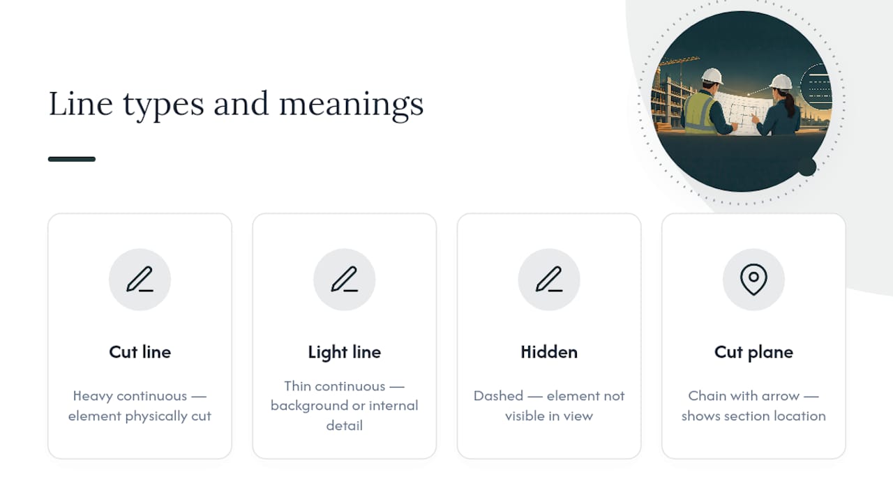
A continuous heavy line generally marks an element that’s been physically cut by the drawing, a wall in section, for instance, or an edge visible in the foreground of the view. A continuous light line shows detail within that cut element, or objects further from the viewer that don’t need the same visual weight. Dashed or hidden lines represent something that exists but isn’t directly visible in that view, structure above a ceiling, foundations below a floor slab, or an existing element being removed.
Centre lines, typically a long dash alternating with a short dash, mark the centre of a symmetrical object or the axis a dimension is measured from. A chain line with a bold section and an arrow indicates a cut plane, the exact line and direction a section drawing has been taken from, which is how you find the matching section sheet for a given plan location.
Dimension lines and their extension lines are thin and light, deliberately, so they don’t compete visually with the building elements themselves. Break lines, a jagged or zigzag mark, show where a drawing has been deliberately cut short because the element continues beyond what needs illustrating.
None of these conventions are difficult individually. The difficulty is holding several in your head at once while reading a busy sheet, which is exactly why checking the legend for anything unfamiliar beats guessing from memory.
How do you interpret material specifications and notes?
A drawing shows you where a wall or a floor sits. It rarely tells you everything required to actually build it, and that gap is where specifications and notes take over.
Specifications set out the actual materials, performance requirements and workmanship standards behind what’s drawn. A wall shown as a single line on plan might correspond to a detailed wall type reference (something like “WT-04”) that specifies the stud size, insulation thickness, fire rating, acoustic performance and exact board layers. Skip that reference and price the wall off the drawn line alone, and the number will be wrong, sometimes significantly.
General notes, usually printed on an early sheet in the set, cover project-wide requirements that would be repetitive to write on every drawing: tolerances, standards being followed, general workmanship clauses, and default assumptions unless a specific note overrides them locally. Always read general notes before relying on a symbol or convention that seems unusual, because the project’s own notes take priority over generic drawing conventions.
Material callouts on a drawing, often a short code or leader line pointing to a material, work the same way as wall type references: they’re pointers to fuller information sitting elsewhere in the specification document. Separating what’s visibly drawn from what’s actually required to build it, fixings, laps, flashings, fire-stopping, temporary works, is essential before pricing anything, because none of those items typically show up as a line on the drawing itself. Treat every material callout as a prompt to go and find the fuller answer, not as the answer itself.
Which industry standards and codes appear on drawings?
Drawings reference a handful of standards repeatedly, and recognising them saves time chasing definitions later.
BS and ISO standards govern representation conventions, line types, symbols, and title block layout, with BS EN ISO 128-2 being the current reference for lines and general representation principles. These standards keep drawings broadly consistent across different practices and countries, though, as covered earlier, project-specific legends still take precedence when the two conflict.
RICS NRM 1 and NRM 2 govern measurement rather than representation: NRM 1 provides the elemental structure for cost plans and order-of-cost estimates, while NRM 2 sets out detailed rules for measuring work for bills of quantities. Any drawing set feeding into a formal cost estimate is implicitly measured against one or both of these.
Approved Documents, published by the UK government, provide practical guidance for meeting Building Regulations requirements, covering everything from structural safety to fire, ventilation, and accessibility. Drawings should always be checked against the applicable Approved Document rather than treated as self-sufficient proof of compliance, since a regulator or building control body can still require additional detail or an alternative solution beyond what’s shown.
You’ll also encounter British Standards for specific systems (drainage, structural steel, timber design) referenced directly in specification notes, usually as a code like “BS 8110” or “BS 5268” sitting next to a material callout. Treat each as a pointer to the governing document, not something to interpret from the drawing alone.
How do you spot errors and discrepancies in drawings?
Discrepancies between sheets are normal on any live project, not a sign of a badly run job, and catching them early is a core part of reading drawings competently rather than a failure of the process.
The most common source is a mismatched revision: one sheet updated, another not, and the two no longer agreeing on a dimension or a layout. Always check that every sheet you’re working from carries the same, or a compatible, revision date before cross-referencing between them.
Dimension conflicts are the next most frequent issue: a written dimension that doesn’t match what you measure with a scale rule, or two dimension strings on the same drawing that don’t add up to the overall figure given. When you find one, don’t average the difference or guess which is right. Note it and raise it as a formal query.
Watch for structural and architectural sheets disagreeing on wall positions, opening sizes, or level datums, since these clashes are expensive if they reach site before anyone notices. A beam shown at one height on the structural sheet and a ceiling shown clashing with it on the architectural sheet is exactly the kind of thing a careful read catches before it becomes a site problem.
Finally, watch for schedules that don’t match the drawings referencing them, a window schedule listing a size that doesn’t match the opening shown on plan, for instance. Schedules are compiled separately from drawings and occasionally drift out of sync, so treat any mismatch as worth a query rather than assuming the schedule is automatically correct.
Field notes: the mistakes that cost the most on site
The single costliest error a beginner makes is working from the wrong issue. Always confirm the sheet number, revision, and date against the drawing register before taking a single measurement, because a superseded drawing looks identical to the current one until the dimensions don’t match on site.
Treat every tag, a door tag, a window reference, a wall type code, as a hyperlink rather than a label. Follow it to its schedule or detail before assuming you know what it specifies; guessing from the symbol alone is how specification errors slip through unnoticed. And remember that drawings show design intent, not regulatory approval. When a detail touches structural safety, fire escape, or accessibility, that’s the point to involve building control or a qualified engineer rather than reading the drawing as the final word.
— Florin
Prefer to hand this to a contractor instead?
Reading a full drawing set carefully takes real time, and plenty of readers get through this checklist and decide the smarter move is handing the drawings to a firm that already lives in them daily. Some building firms offer faster quoting processes and virtual tours of projects before you commit, allowing you to judge workmanship rather than just viewing a portfolio of finished photos.

That transparency runs through the residential building services Evostruct delivers across loft conversions, extensions and garden rooms, and through the dedicated home extension work covering rear, side return and wraparound projects. If your drawings are for a commercial fit-out or small infrastructure job rather than a home, the commercial building services team works from the same fast-quote model. Once you’ve reviewed your own drawing set and understand your project requirements, consider requesting a detailed quote and viewing live projects before making a decision.
Where to go next for standards and training
A handful of sources cover almost everything a beginner needs once this checklist stops being enough on its own.
RICS NRM 1 and NRM 2 — the governing rules for order-of-cost estimating and detailed bill-of-quantities measurement in the UK.
BS EN ISO 128-2 — the current standard for line conventions and general representation in technical drawings.
Gov — practical guidance for meeting Building Regulations requirements, sheet by sheet.
Plan Reading and Specifications on Coursera — a structured beginner course covering the full drawing set and how the disciplines interact.
Navigating construction documentation, GreenBuildingAdvisor — practical, plain-English advice on tracing elements across a set.
Sources
FAQ
Is reading construction plans hard?
It’s a learnable skill rather than an innate talent, and most of the difficulty is unfamiliarity with symbols and cross-referencing rather than complexity. Beginners who trace individual elements across plan, elevation, section and schedule on a couple of residential sets usually get comfortable within a handful of practice sessions.
What are the main types of construction drawings?
A typical set covers site and civil drawings, architectural plans, elevations, sections and details, structural drawings, and mechanical, electrical and plumbing (MEP) drawings, alongside schedules for doors, windows, and finishes. A coordinated set organises these by discipline prefix and reads best in that same sequence, from cover sheet through to services.
Is there an app that reads blueprints for you?
Apps and BIM viewers can help with searching, measuring, annotating and comparing PDF sheets, which speeds up navigation considerably. They don’t replace interpreting notes, specifications and site conditions yourself, and automated quantity extraction still needs professional checking before it’s relied on for a real quote.
How do you read structural drawings specifically?
Start with the structural drawing index and general notes, then locate the gridlines and datums that tie the structural sheets back to the architectural plan. From there, trace foundations up through columns and beams, checking every reinforcement tag against its schedule, and cross-check anything that touches openings or ceiling voids against the architectural drawings before assuming it’s resolved.
Does Evostruct provide quotes based on existing drawings?
Yes. Evostruct reviews submitted drawings and specifications to produce a detailed, itemised quote for loft conversions, extensions, garden rooms and similar residential projects listed on its residential building services page. Exact pricing depends on project scope and is confirmed after that review, though published starting figures are available on the relevant service pages.

Comments